Friday, October 28, 2016

OSPF routing between Cisco Router and Mikrotik Router

For this I have used GNS3 for cisco router and Virtual box for mikrotic router. Cisco router in GNS3 is connected to a host which is configured by my LAN card adapter. Mikrotic router  is connected to also LAN  by bridging in virtualbox.
GNS3 Settings

Virtual box setting
C

Cisco Router IP                                           Mikrotic Router IP
      G0/0: 192.168.0.60/24                                 ether1: 192.168.0.50/24
      loopback1: 2.2.2.2/24                                    loopback1:1.1.1.1/24
      ospf area 400                                                 ospf area id: 0.0.1.144
                                                                           
Area ID calculation in Mikrotic, convert 400 decimal into binary (i.e. 110010000). The binary number needs to show 32 digits, representing the digits of the 4 octets in the IP type format. So, 110010000 binary = 00000000.00000000.0000001.10010000 as broken into octets. Finally, convert each octet into a decimal value. (e.g. 00000000.00000000.0000001.10010000 = 0.0.1.144). Therefore, 400 = 0.0.1.144
Command in Cisco 
R1>ena
R1#conf t
R1(config)#int loopback 1
R1(config-if)#ip address 2.2.2.0 255.255.255.0
R1(config-if)#no shut
R1(config)#int G0/0 
R1(config-if)#ip address 192.168.1.0 255.255.255.0
R1(config-if)#no shut

R1(config)#router ospf 1
R1(config-router)#network 192.168.0.0 0.0.0.255 area 400
R1(config-router)#network 2.2.2.0 0.0.0.255 area 400
R1(config-router)#

Command in Mikrotic


[jahid@MikroTik] >
[jahid@MikroTik] > interface bridge add name=loopback1
[jahid@MikroTik] > ip address add address=1.1.1.1/24 interface=loopback1
[jahid@MikroTik] > ip address add address=192.168.0.50/30 interface=ether1
[jahid@MikroTik] >
[jahid@MikroTik] > routing ospf
[jahid@MikroTik] /routing ospf> area add name=area400 area-id=0.0.1.144
[jahid@MikroTik] /routing ospf> network add network=192.168.0.0/24 area=

Area ::= area1 | area2 | area5 | area400 | limon | ...

[jahid@MikroTik] /routing ospf> network add network=192.168.0.0/24 area=area400
[jahid@MikroTik] >
[jahid@MikroTik] >

Then Checking in cisco


Then Checking in Mikrotik


Thank you everybody. 


Tuesday, October 25, 2016

NTP Configuration in Cisco Router

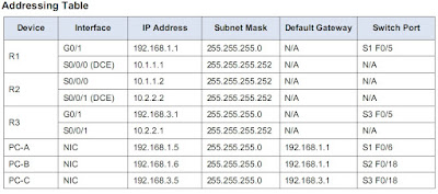
The NTP Server is the master NTP server in this activity. You will configure authentication on the NTP server and the routers. You will configure the routers to allow the software clock to be synchronized by NTP to the time server. Also, you will configure the routers to periodically update the hardware clock with the time learned from NTP.


Configuring NTP 

Step 1: Enable NTP authentication on PC-A. 

On PC-A, click NTP under the Services tab to verify NTP service is enabled.
To configure NTP authentication, click Enable under Authentication. Use key 1 and password NTPpa55

Step 2: Configure R1, R2, and R3 as NTP clients. 

R1(config)# ntp server 192.168.1.5
R2(config)# ntp server 192.168.1.5
R3(config)# ntp server 192.168.1.5

Verify client configuration using the command show ntp status.

Step 3: Configure routers to update hardware clock. 

Configure R1, R2, and R3 to periodically update the hardware clock with the time learned from NTP.
R1(config)# ntp update-calendar
R2(config)# ntp update-calendar
R3(config)# ntp update-calendar
Exit global configuration and verify that the hardware clock was updated using the command show clock.

Step 4: Configure NTP authentication on the routers. 

Configure NTP authentication on R1, R2, and R3 using key 1 and password NTPpa55.
R1(config)# ntp authenticate
R1(config)# ntp trusted-key 1
R1(config)# ntp authentication-key 1 md5 NTPpa55

R2(config)# ntp authenticate
R2(config)# ntp trusted-key 1
R2(config)# ntp authentication-key 1 md5 NTPpa55

R3(config)# ntp authenticate
R3(config)# ntp trusted-key 1
R3(config)# ntp authentication-key 1 md5 NTPpa55

Step 5: Configure routers to timestamp log messages. 

Configure timestamp service for logging on the routers.
R1(config)# service timestamps log datetime msec
R2(config)# service timestamps log datetime msec
R3(config)# service timestamps log datetime msec

Then this command is used to show the current time
R1(config)#show clock
or
R1(config)#show clock details